No room for your base antenna? Try a dipole
| My first CB antenna was a Antron 99 which I haphazardly mounted on top of a 75 foot cedar tree after making a death defying climb. I was 16 years old at the time.
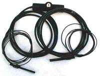
After attending college, getting married and moving into a small basement apartment the CB bug really bit me again. I pulled out my old Realistic TRC-434 40 channel AM base station and stated making plans for setting up my station. I had the radio and the coax, but what I was lacking was an antenna. My old Antron 99 was, and still is located near the top of that original cedar tree which has grown around the antenna making it a permanent fixture of nature. Not that it would have mattered though, my landlords would never have agreed to let me put up a vertical antenna. Just as I was about to give up on putting together my base station idea, I came across an article on the internet about dipole antennas. Now I hadnt made a dipole antenna since I was 15 years old and hadnt even really considered that as an option, but after reading about different dipole configurations I started to realize that it was the perfect antenna for my problematic situation. I was studying a number of different ways to build a dipole antenna when a friend suggested I should just pick up one of the pre-made Bazooka Dipole antennas from Radiowavz. I looked into it and sure enough the total cost of the antenna was $30 which included shipping and it was better made and more weatherproof than anything I could have fabricated for $30 (I thought back to some of my former dipole projects which worked great, but were not a pretty sight).
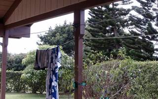
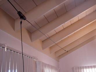
My antenna arrived and I was quite impressed with its design and manufacture. These antennas from Radiowavz are very well made with quality materials and are sealed very well. Many people didnt understand paying for a dipole when its so easy to make one yourself, but once you see one of these Radiowavz dipole antennas youll find that for the amount of time and money it would take to make your own dipole of this quality it really is a smart buy. Now it was time to install the antenna. We lived on the bottom floor of the house and had a small 6 foot x 20 foot fenced area that was our yard. My lease didnt allow me to put up any antennas so I had to be very careful about placement so that no one would see the dipole. I ended up mounting the antenna along the top of the wooden fence in a horizontal configuration. It was very inconspicuous and about 3 above the top of the fence. I got my base ready then connected the coax and SWR meter and had my first key for SWR. Its was over 3 so I knew that I had some work to do. I was ready to trim the ends of the antenna when another friend recommended just bending back the ends upon themselves and taping them together until I found a good SWR reading. That way if I moved the antenna into another configuration in the future I could undo the ends to make it longer if necessary. I wasnt sure how well this would work but sure enough with about 6 of each end on the dipole taped backwards I had a 1.2 SWR across all 40 channels. I could hear the locals right away on Channel 18 (the local BC AM channel) and thought Id give them a shout from the base. I had no problem reaching them although they said my signal was a S3 when normally from my vehicle with a 102 at the same location I was doing a S5. The receive on the dipole was excellent and there was almost no static at all. I used the antenna in this configuration for a couple of months and also experimented with an inverted V configuration with good results as well. Everyone in the local area was very surprised that a 4 watt radio and dipole antenna could perform so well locally. The antenna was only about 6.5 feet above the ground! The most amazing thing I found when using my dipole what that it created almost no TVI and I could watch football and talk on the radio without any worry of snow on the TV. When we moved later that year I took down my antenna and boxed it up thinking that I wouldnt use it again for a long time. Although a dipole can do surprisingly well it cant compete with a well made base antenna. Our move took us to beautiful Hawaii and we lived in an apartment for the next year so any chance of a base station was out of the question. Hawaii is a great place for DXing and I was making contacts to Australia almost daily in the mobile so I couldnt wait to set up a base station. We moved into a rental home but once again it was a situation where a vertical antenna wasnt going to be tolerated. I dug out my trusty dipole and temporarily hung it in the car port horizontally between the two supporting beams. It was only about 7 above the cement driveway and very well disguised as it ran just above the wire clothes line.
With a Magnum Omegaforce radio on a 10 amp power supply I was talking skip everywhere within minutes. I talked to the mainland on many occasions and it seemed like I had a direct pipe to Australia as I talked to them everyday for months. Often I would be talking to a loud Australia station who was using a multi element beam with 100 watts output and they could not believe how well my dipole only feet above the ground with 30 watts was performing. My SWR was always under 1.5 and because I didnt want my landlord to know about the antenna, after talking each day I would unscrew my coax and pull it inside the house. At one point I even mounted the antenna inside to see how it would perform. I was able to talk to Australia and Chicago in the same day.
Im hoping that at our next home Ill be able to mount a larger base antenna, maybe a 5/8 or a beam. Its nice to know though that no matter where we move, my trusty dipole is always an option. After 5 years of being moved around and battered by the sun, rain and wind of both the Northwest and Hawaii the antenna looks new and performs as good as the day I bought it. So should everyone make a dipole or buy one? Of course not, but if you have no other options available you might be surprised at what it can do. I know I was. |